Astable 555 Timer Schematic / 555 Timer Ic As Amv Astable Multivibrator M3l4 Youtube / Basic 555 astable multivibrator circuit.. Basic 555 astable multivibrator circuit. To observe the 555 timer in astable mode, let's build a circuit that uses the 555 timer's oscillating output to make an led flash on and off: No external triggering is required in astable mode, it automatically interchange its two states on a particular interval, hence generates a rectangular waveform. 555 timer astable multivibrator circuit diagram from circuitdigest.com with this information you will learn how how the 555 works and will have the experience to build some. The 555 timer chip has been a staple of electronics tinkerers for decades as it can be configured into a wide range of different modes with just a handful of external components.
The general 555 timer circuit schematic at the heart of the circuit is a lm555 ic, which includes 23 transistors, 2 diodes and 16 resistors on a silicon. The output from the 555 timer in monostable mode is normally low. So we have a signal with a frequency of about 60hz. When the 555 timer is in astable mode it means that the output will never be stable. In this mode, the circuit of the ic 555 timer produces the continuous pulses with exact frequency primarily based on the value of the two resistors and.
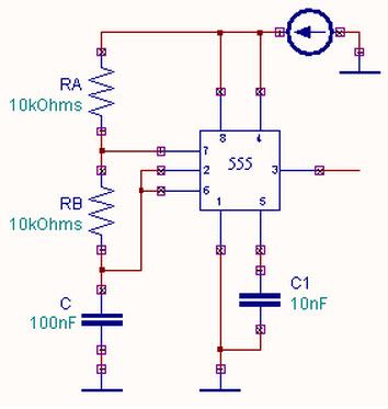
Astable Multivibrator Using A 555 Timer Ic Working from www.elprocus.com To understand the working of the 555 timer in astable mode, take a look at the internal circuit of. When in the charging mode, the capacitor charges through r1 and r2, and its voltage approaches +5v. Unlike monostable multivibrator mode it doesn't have any stable state, it has two quasi stable state (high and low). 555 timer ic schematic diagram / astable multivibrator using 555 timer circuit diagram / if you would like to use any of these ideas, do some testing before using the lm555 or lm556 timer in an actual circuit. A collection of 555 circuits using the 555 timer as an astable oscillator with different duty cycles. Here the time period is the total time it takes to complete one on/off cycle (t 1 +t 2), while duty cycle is the percentage of total time for which the. There are a lot of projects out there using the 555. No external triggering is required in astable mode, it automatically interchange its two states on a particular interval, hence generates a rectangular waveform.
Larger values will make the led blink slower, while smaller values will make the led blink faster.
Basic 555 astable multivibrator circuit. The rc timing circuit incorporates r 1 , r 2 and c. Here the time period is the total time it takes to complete one on/off cycle (t 1 +t 2), while duty cycle is the percentage of total time for which the. Unlike monostable multivibrator mode it doesn't have any stable state, it has two quasi stable state (high and low). This circuit shows an intruder alarm using 555 timer. The 555 timer is capable of being used in astable and monostable circuits. Astable mode, monostable mode and bistable mode are the three modes of operation of ic 555. Each mode represents a different type of circuit that has a particular output. The 555 timer chip has been a staple of electronics tinkerers for decades as it can be configured into a wide range of different modes with just a handful of external components. Awesome 555 timer ic projects · 1. 555 timer astable mode circuit diagram. Here, the capacitor c1 holds charge. 555 timer astable multivibrator circuit diagram from circuitdigest.com with this information you will learn how how the 555 works and will have the experience to build some.
While the capacitor is charging, the output is high. When the voltage across c1 reaches 2/3 of the supply voltage. That means it works as an oscillator. In this mode, the circuit of the ic 555 timer produces the continuous pulses with exact frequency primarily based on the value of the two resistors and. The 555 timer is capable of being used in astable and monostable circuits.
555 Timer 50 Duty Cycle Astable Multivibrator Control Voltage Set To Vcc 38 Khz Multisim Live from s3.amazonaws.com In astable mode, capacitor c1 charges through resistors r1 and r2. 555 timer ic schematic diagram / astable multivibrator using 555 timer circuit diagram / if you would like to use any of these ideas, do some testing before using the lm555 or lm556 timer in an actual circuit. The clock circuit that will produce 60hz clock signals using a 555 timer is shown below. The 555 timer is capable of being used in astable and monostable circuits. The following schematic depicts the internal circuit of the ic 555 operating in astable mode. To understand the working of the 555 timer in astable mode, take a look at the internal circuit of. No external triggering is required in astable mode, it automatically interchange its two states on a particular interval, hence generates a rectangular waveform. While the capacitor is charging, the output is high.
Each mode of operation indicates a circuit diagram and its output.
The 555 timer shown above is configured as an astable circuit. When the 555 timer is in astable mode it means that the output will never be stable. Jun 26, 2021 #1 hi, i'm trying to build a 555 timer circuit that has an output low time of 5 minutes and an output high time of 250 milliseconds. Each mode of operation indicates a circuit diagram and its output. Unlike monostable multivibrator mode it doesn't have any stable state, it has two quasi stable state (high and low). As discussed in the above section, the ic is in its standard monostable mode. 555 timer astable circuit example The 555 ic timer circuit above shows a very straightforward design where the ic 555 forms the central controlling part of the circuit. Resistor r3 is just there to limit the. To observe the 555 timer in astable mode, let's build a circuit that uses the 555 timer's oscillating output to make an led flash on and off: 555 timer astable circuit calculator in this 555 timer astable calculator , enter the values of timing capacitor c and timing resistors r1 & r2 to calculate the frequency, period and duty cycle. Awesome 555 timer ic projects · 1. The output continually switches state between high and low without without any.
The following schematic depicts the internal circuit of the ic 555 operating in astable mode. Awesome 555 timer ic projects · 1. Astable 555 timer circuit for long duration. A collection of 555 circuits using the 555 timer as an astable oscillator with different duty cycles. Complete 555 timer circuit reset switch.
555 Timer As Astable Multivibrator Easy Electronics from www.circuitstoday.com The 555 timer chip has been a staple of electronics tinkerers for decades as it can be configured into a wide range of different modes with just a handful of external components. A collection of 555 circuits using the 555 timer as an astable oscillator with different duty cycles. Here, the capacitor c1 holds charge. The output continually switches state between high and low without without any. Larger values will make the led blink slower, while smaller values will make the led blink faster. 555 timer astable mode circuit diagram. Design of an astable multivibrator using 555 timer ic,. 555 timer ic schematic diagram / astable multivibrator using 555 timer circuit diagram / if you would like to use any of these ideas, do some testing before using the lm555 or lm556 timer in an actual circuit.
As discussed in the above section, the ic is in its standard monostable mode.
Because of their availability and ease of use, the 555 astable circuit is the common source of clock signal in many synchronous circuits. Astable mode, monostable mode and bistable mode are the three modes of operation of ic 555. Pin 1 connects to 0v. The 555 has three main operating modes, monostable, astable, and bistable. Here the time period is the total time it takes to complete one on/off cycle (t 1 +t 2), while duty cycle is the percentage of total time for which the. 555 timer for dc to dc converter circuit for more. Each mode of operation indicates a circuit diagram and its output. When the 555 timer is in astable mode it means that the output will never be stable. The following image shows a simplified circuit of 555 timer ic in astable mode. Nov 05, 2011 · they have over 70,000+ readily available schematic in their web database along with 15,000+ pspice libraries. The 555 timer ic is an integrated circuit (chip) used in a variety of timer, delay, pulse generation, and oscillator applications. As well as being used to construct astable oscillators, it can also be used in monostable mode where an input pulse is used to trigger a time delay set by an rc time. This 555 timer is in astable mode.
This circuit shows an intruder alarm using 555 timer 555 timer schematic. Resistor r3 is just there to limit the.


0 Komentar